Engineering
Mining Starlink for Radar ideas


Disclaimer: This post mentions Starlink but I have no association with Starlink. This post is merely explorative in nature, and deals with radar-related challenges in a computer game setting - not real life. Nothing in this post should be treated as official Starlink information - we’re just exploring ideas.
Note: Shout out to 0xWUT for the brilliant suggestion to mine the Starlink paper for ideas.
The radar Rust crate tries to provide some
realism to game radar. It simulates what a radar operator actually sees. It has a scanning beam, detection from the radar range equation, noisy measurements, false alarms, and tracks that form, coast and drop. Another Rust crate, robocode, uses the radar crate for realistic scanning, but radar is entirely monostatic: one site transmits and the same site listens.
A few days ago I shared the release of radar on Twitter. The account 0xWUT kindly suggested that I could try and source ideas for improvements from a paper it linked to - which I did. This post is the result of that process.
We’ll start by identifying a core shortcoming of the current radar crate, and then look at how the Starlink paper was mined for ideas that could potentially be ported over to the radar crate.
Let’s go.
The paper and The problem
Ya, so the Starlink paper was suggested for idea-mining. I had some problem getting hold of the actual paper, but eventually found it through my University library. The paper in question is:
P. Gomez-del-Hoyo, K. Gronowski and P. Samczynski, “The STARLINK-based passive radar: preliminary study and first illuminator signal measurements”, International Radar Symposium (IRS), 2022.
From the paper’s abstract we learn:
“Abstract—In this paper, a preliminary study for the design of
passive radar exploiting novel space illuminators of opportunity
is presented. Wide-band satellite systems such as the Starlink
constellation have arisen as promising illumination sources for
passive coherent location due to their almost ubiquitous presence
and transmission characteristics. In this work, the potentials
of Starlink transmitters as illuminators of opportunity are
described, presenting an overview of the Starlink constellation,
signal transmission characteristics, and real Starlink reference
signals acquired at Warsaw University of Technology (WUT).”
Terminology to get us going
The following concepts are needed to follow along:
- Passive Radar - is a radar system that does not transmit its own electromagnetic signals.
- Illuminator - an illuminator of opportunity is an existing transmitter whose signals can be exploited for radar purposes.
- Passive Coherent Location - a PCL is a passive radar technique that uses two types of received signals: 1) A reference signal: the signal received directly from the satellite, without reflecting off a target, 2) A surveillance signal: the signal reflected from an object, such as an aircraft.
Let’s begin by highlighting a de facto limitation - a passive radar has no transmitter.
It listens to someone else’s signal (an illuminator of opportunity) and detects the echoes that targets scatter toward the receiver. Transmitter and receiver are in different places, so the
geometry is bistatic - a core term for the rest of this post.
WiP: Clarify consequece of radar being bistatic.
The authors of the paper asks whether Starlink’s Ku-band downlink makes a good illuminator (see terminology aboce). They compare Starlink with GPS, Galileo and DVB-S2 satellite TV using a bistatic SNR equation (eq. 1 in the paper). They finds that Starlink’s low orbit (550 km) and wide 250 MHz channels win easily: a 40 m² truck is detectable to about 18 km, against under 7 km for the runner-up, Galileo E5. The paper works out the bistatic range resolution (eq. 2), maps coverage for three receiving antennas, and sketches a hardware front end.
Mining for Radar Topics
I started from a list of eight radar topics and checked each against what the paper actually provides. Adjacent topics were merged into GitHub Pull Requests, PR:
| Topic | What the paper offers | Outcome |
|---|---|---|
| Radar range equation | Eq. (1), bistatic, EIRP-driven | PR 1 |
| Radar resolution | Eq. (2), bistatic and aspect angles | PR 2 |
| Detection probability | A fixed 16.5 dB threshold | PR 3 (merged with the next row) |
| Target detection | Threshold, target RCS | PR 3 |
| Coverage estimation | Detection range vs RCS, antennas, coverage maps | PR 4 |
| False alarms and noise | Only thermal noise kT₀Bₙ |
PR 5 (merged with the next row) |
| Noise and interference | Only thermal noise and losses | PR 5 |
| Target tracking | A mention of Doppler drift | Dropped |
So, eight topics became five GitHub Pull Requests. Detection probability and target detection were
one idea in two names, and so were the two noise topics.
Target Tracking was dropped because the paper gives almost nothing to build on, and inventing it wouldn’t be “sourced from the paper” any more.
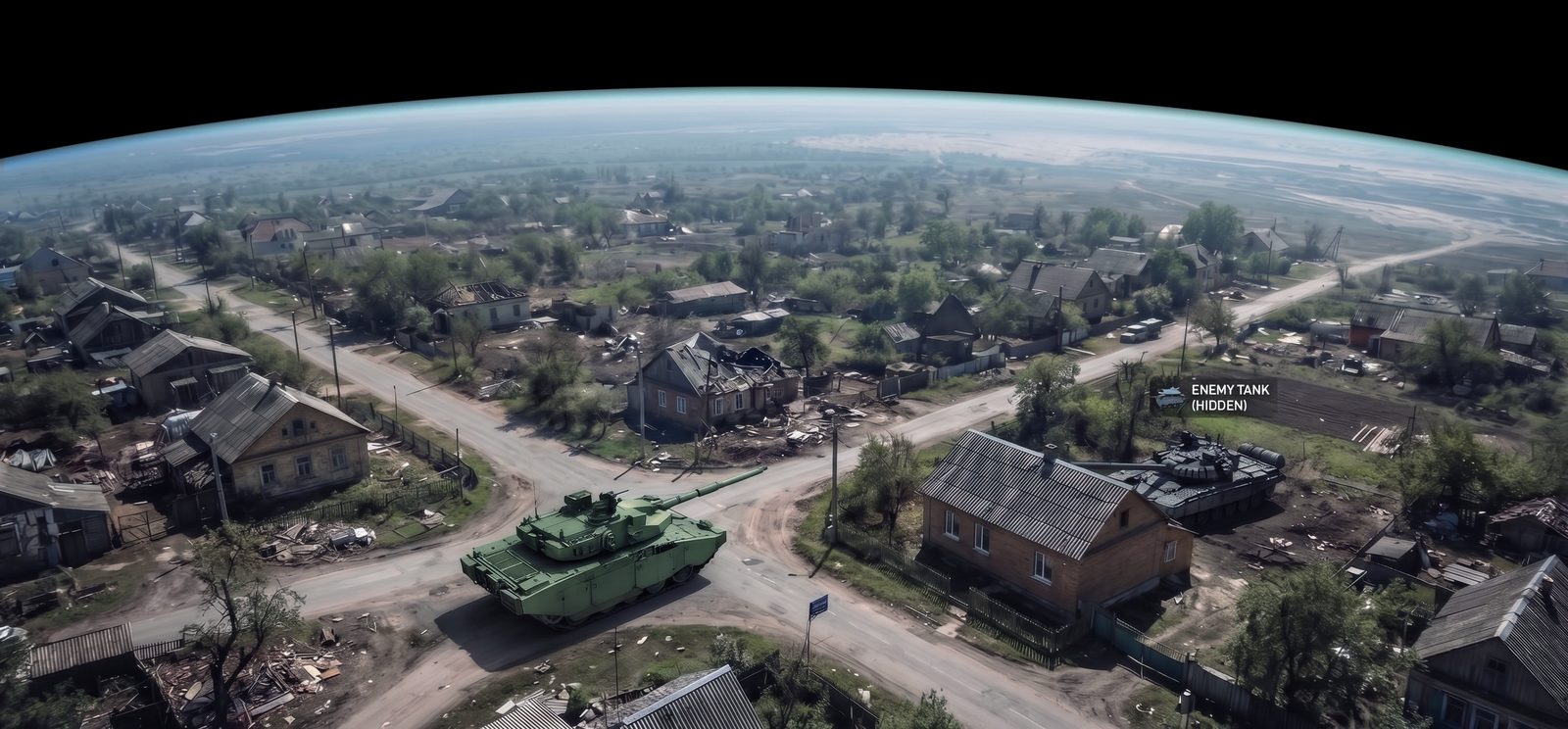
A friendly tank unware of the enemy tank hidden behind the house.
From Topics to Pull Requests
The current version of the radar crate, v0.2.0, has no notion of a transmitter and receiver in different places, so everything lives in a new, purely analytic module, radar::bistatic.
These are the five Pull Requests that are likely to be merged in the next release:
- Illuminators and the range equation
Illuminatorpresets come from the paper’s Table II: Starlink, GPS L1 C/A and L5, Galileo E1 and E5, and DVB-S2.BistaticGeometryprovides two ranges, the baseline, the bistatic range, and the bistatic angle β with its bisector.PassiveReceiverevaluates eq. (1) with coherent processing gainB·T. - Resolution and Doppler
Eq. (2),ΔR = c / (2B·cos(β/2)·cos ψ), plus velocity resolution and the echo’s Doppler with a moving transmitter. A low-orbit satellite shifts the echo of even a parked car, which the paper calls out. - Detection
The paper’s fixed 16.5 dB threshold, plus a proper false-alarm-rate detector with detection probability for Swerling 0, 1 and 3 targets. - Coverage
Maximum detection range in closed form, the paper’s three surveillance
antennas (a 40 dBi parabola, a 17 dBi horn and a 24 dBi five-horn array),
and a
CoverageMapof SNR and range resolution over a grid. - Noise and false alarms
The paper stops at thermal noise, so this PR uses textbook material: direct-signal interference (the satellite leaking straight into the surveillance antenna) with cancellation, SINR, range-Doppler cell counts, and cell-averaging CFAR.
Testing Code against Paper Data
A paper is a good source of ideas and a good source of test cases. Each PR checks itself against a figure or table:
- Table II. Every preset’s power flux density at the ground,
EIRP / 4πR², lands within 1 dB of the paper’s column (−98 dBW/m² for Starlink, −131 for GPS L1). - Detection ranges. Plugging the paper’s parameters into eq. (1) gave 31 km for the 40 m² truck, not the paper’s 18 km. The gap is a constant 4.74 dB, and the paper never states its losses. With that one number added, all its ranges come back: 18 km for 40 m², 2.8 km for 1 m², and under 7 km for Galileo E5. The tests pin those.
- Wavelength. Table II rounds Starlink’s wavelength to 0.03 m. The real 11.7 GHz carrier is 0.0256 m, which gives 15.4 km instead of 18. The tests that reproduce the paper use its rounded value; the presets use the real one.
- Fig. 8, the antennas. From peak gain alone, the parabola reaches 18 km, the array 2.85 km and the horn 1.27 km. The paper shows about 3.1 and 1.4 km for the two horns, roughly 10% higher, and the test says so rather than hiding it.
- Fig. 6, resolution. At 50° and 80° satellite elevation, every cell within ±10 km stays under 3 m (the worst is 1.4 m), and the worst cells point toward the satellite, as in the paper.
Section V’s “range resolution stays below 3 m”, or Fig. 8’s “1.4 km for a horn”, are exactly the claims that make good regression tests.
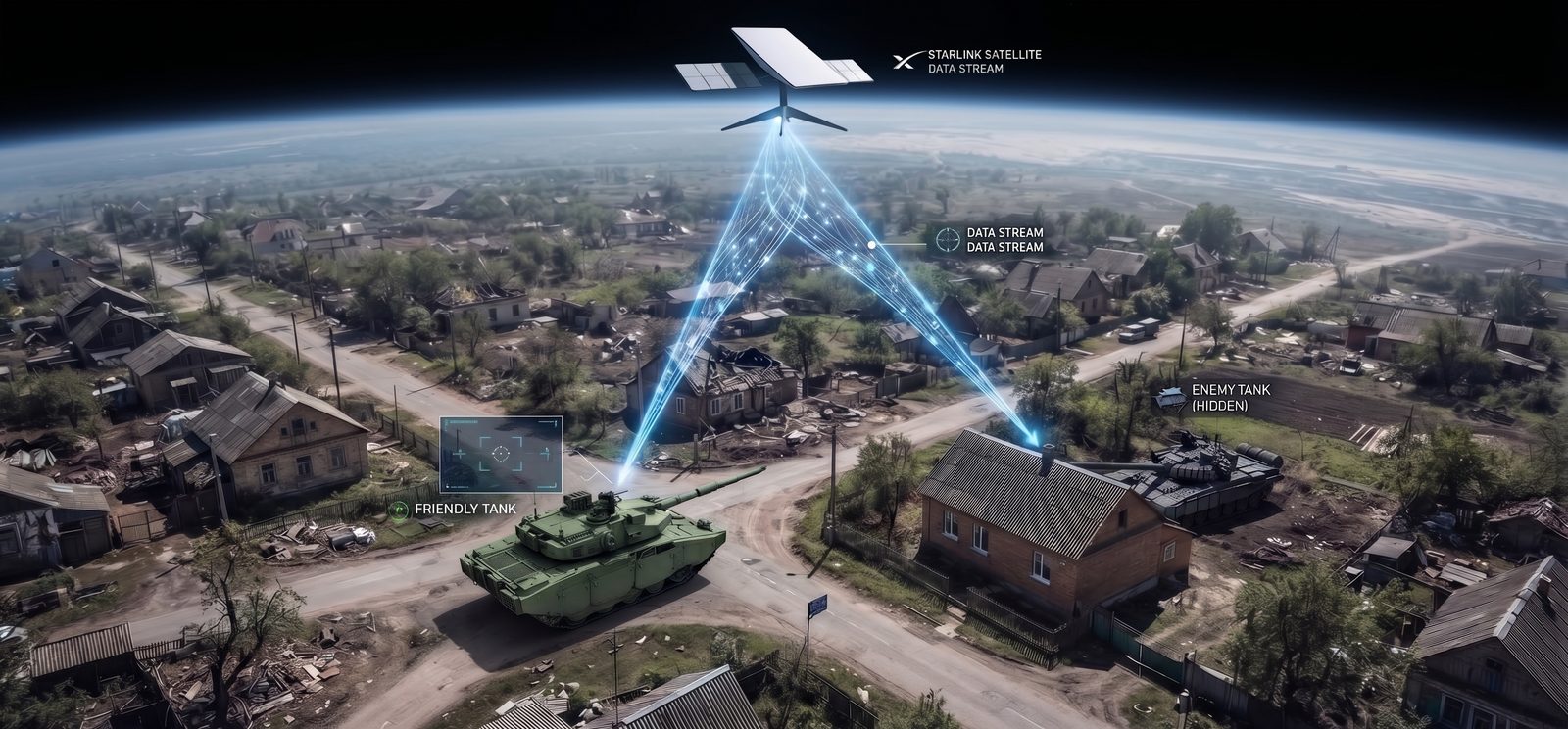
Starlink as the illuminator: the echo from a hidden enemy hidden tank is relayed to the friendly tank.
Use Case: The Ginza Battle
The RoboCheck page has a battle set in Ginza, Tokyo. The map this battle was fought on was built from OpenStreetMap at 4 px per metre: 1200 × 600 px of arena is 300 × 150 m of real city, with 58 buildings from 17 to 51 m tall covering 53% of the ground. (I have since rebuilt the map from PLATEAU building outlines and measured heights. I haven’t re-run the measurements below on the new map.) Four tanks take part: the RoboCheck Candidate (verified to follow rules S1–S3) against Tactician, Circler and SafeShooter. Bullets are realistic, and the battle runs 2,000 turns with no winner.
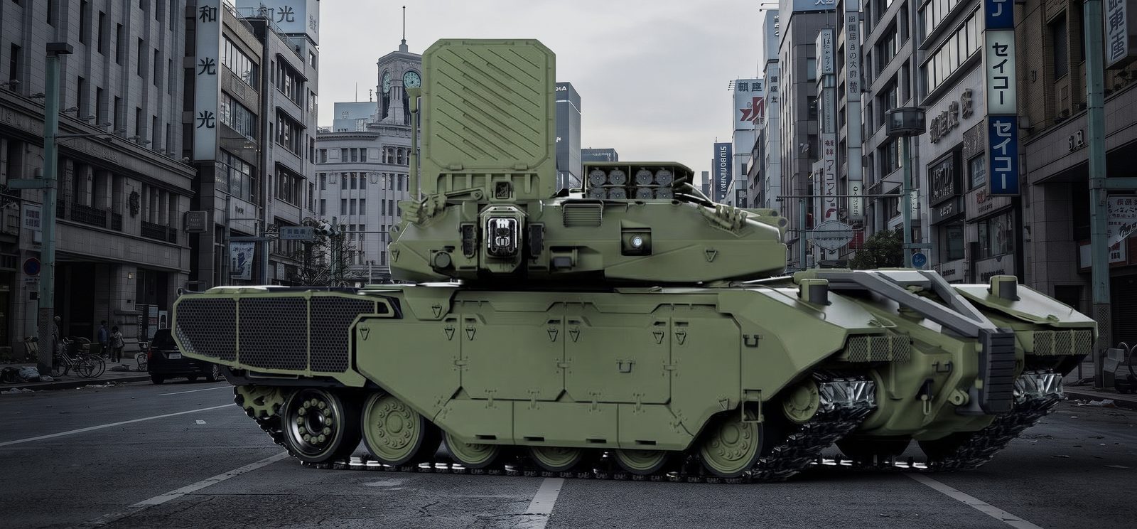
An imaginary tank equiped with its own radar and equiped with a Starlink receiver - parked in the middle of a street in Ginza, Japan.
I replayed the recording and measured what the radar had to work with:
- Line of sight is rare. Across all pairs of living robots, only 11% of robot-pair turns had a clear line between them. Buildings block the rest.
- The Candidate never saw anyone. In 2,000 turns it had line of sight to no one. It never had a target, never fired, and never moved from its starting spot at (40, 40). (That spot is 40 px from two walls, while S3 forbids driving within 80 px of a wall. Freezing in place is a RoboCheck story, not a radar one, but it means a better radar wouldn’t have saved it.)
- Tactician saw exactly what it could see. It had a target “seen this turn” in 476 turns, against 506 turns of line of sight to its opponents.
- Every shot hit. 61 shots were fired and 59 hit, a 97% hit rate.
Before the PRs: perfect eyes, blocked by walls
Robocode’s radar here is binary and exact. If a robot is in the beam and nothing blocks the line, the scanner learns its exact bearing and distance. Otherwise it learns nothing. Ginza shows both halves of that:
- Buildings are the only limit. Line of sight explains almost all of Tactician’s 476 turns of sight. Range, power and noise play no part.
- What you do see, you see perfectly. A 97% hit rate is what exact bearings and ranges buy you. A real radar would hand back a noisy plot, a missed look, or a false alarm.
The unmerged radar-seam branch moves robocode onto the radar crate, which
adds detection probability, measurement noise and tracks. That would have
taken the edge off the 97%. But it is still a monostatic radar that needs line
of sight, so in Ginza the Candidate would still be blind.
After the PRs: what passive radar would and wouldn’t change
Suppose each tank carried a passive receiver listening to Starlink.
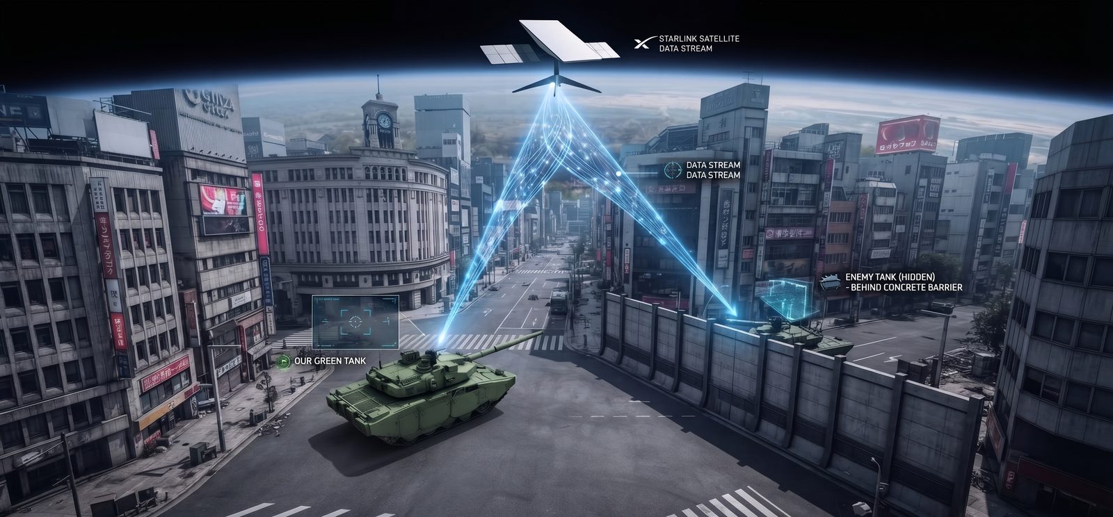
A friendly tank is alerted of an enemy tank hidden behind a concrete barrier.
The link budget stops mattering. Starlink detects a 40 m² target to about 15 km, and Ginza’s longest diagonal is 335 m. Every tank with a clear path is tens of dB above the 16.5 dB threshold. Range resolution, 0.6 m for a monostatic geometry and at most 1.4 m bistatic, is far finer than a tank (about 9 m). In this arena, what limits detection is geometry, not signal.
Passive radar needs two clear paths, not one. The echo has to get from the satellite to the target, and then from the target to the receiver. The second path is the same line of sight Ginza already rations. The first is new: tall buildings cast radio shadows. Tracing rays from every open 10 px cell toward the satellite, the share of Ginza’s open ground the satellite can’t reach is:
| Satellite elevation | Ground in shadow |
|---|---|
| 80° (near overhead) | 9–13% |
| 50° | 31–37% |
| 25° | 45–48% |
The ranges cover a satellite to the north or to the south. So a passive radar in Ginza would see less than today’s model, and how much less depends on where the satellite is. A Starlink satellite crosses the sky in minutes (the paper’s Fig. 2b), so the shadows sweep across the streets as it passes.
False alarms would be manageable. Ginza’s range-Doppler map is small: about 560 range bins over 335 m, times about 1,560 Doppler bins for targets up to 20 m/s. That’s roughly 0.9 million cells, so a per-cell false-alarm probability of 1e-6 means about one false alarm per processing interval. That is easy to filter. The same radar over a 30 km area would face about 195.
Direct-signal leakage is harmless here. Through a 10 dBi sidelobe, the satellite’s own signal arrives about 11 dB below the noise. Pointing the main beam at the satellite would put it 19 dB above the noise, which is what PR 5’s cancellation is for.
Shortcomings and Feature Ideas
The Ginza Battle use case is useful because it breaks the PRs in exactly the places they don’t model - here are some of the shortcommings of the five Pull Requests:
CoverageMapassumes open sky. Run over Ginza, it would report every street covered, while in reality robot pairs can’t see each other 89% of the time and up to half the ground is in satellite shadow. The crate already has anEnvironmenttrait for line-of-sight occlusion. The next step is to test both legs against it: satellite to target, and target to receiver.- No clutter or multipath. Ginza is glass and concrete. A real passive radar there is limited by echoes off buildings, not by thermal noise. PR 5 treats all interference as noise, which is optimistic in a city.
- No tracking. Tracking was the topic that was dropped, and it’s what Ginza needs most. A robot that can see someone 11% of the time lives or dies on coasting a track through the gaps. PR 2’s Doppler functions are the building blocks.
- It’s analytic, not simulated.
radar::bistaticcomputes link budgets.Simulationradars are still monostatic, so no robot can carry a passive receiver yet. - Shadows move. A low-orbit illuminator changes elevation within a single battle. A faithful model has to move the satellite and re-test shadowing every turn.
Ideas for features
Mining the paper for radar ideas gave us an idea for a feature that we’ll try to add to robocode in the near future. Even if a tank is alerted about the exitence of an nearby hidden enemy tank, that doesn’t mean that it has weoponry to strike it.
By deploying a drone, the tank could use the provided target information an operate
a drone strike on the enemy tank that was identified by starlink.
But that would require that we first model tank-to-drone communication and control.
So, that’s probably what we’ll do next.
Accoustic identification of drones is somewhat related to radar, so that might be another feature that is worth exploring in the future.
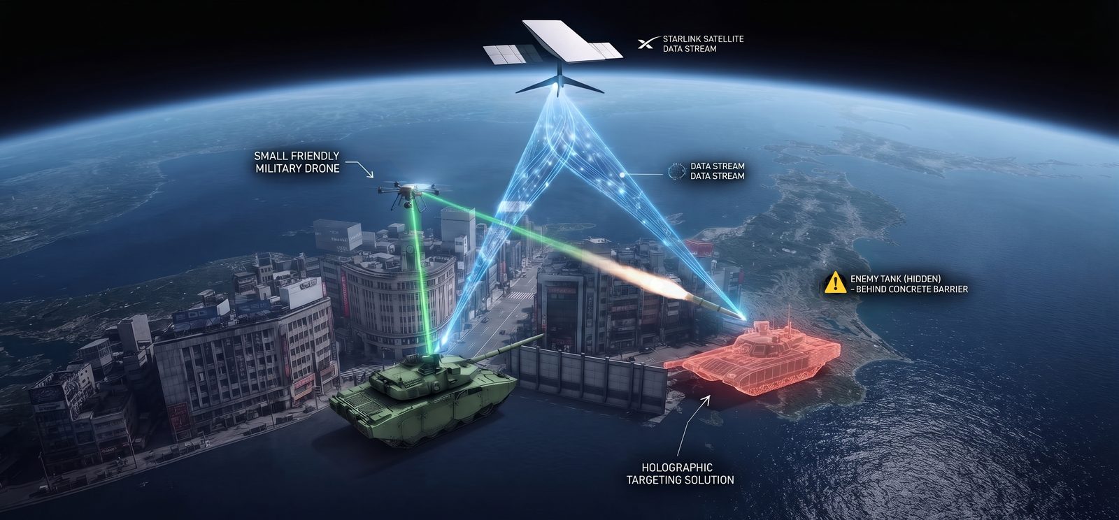
A holographic targeting package, where a friendly tank is provided with location data of an enemy tank hiding behind a barrier, enabling the tank to deploy, and FPV-direct, a drone as countermeasure.
Acknowledgement: Use of AI
I know that some people appreciate acknowledgements which clarify to what extent AI was used in producing the artifact at hand. I’ve personally lost interest in tracking this, since the use of AI is pretty much everywhere at this point. Anyway, for the sake of clarity, this is how AI was used:
- A suggestion was made to source radar ideas from an academic paper.
- The paper was downloaded form the Internet.
- Claude was then asked to analyze the
radarcrate, in order to get a sense of its intended use and scope of its features. - Claude was asked to analyze the academic paper with the goal of searching for potential features that could be added to the crate.
- Once Claude had identified a few such features, the AI was asked to reduce the potential candidates to one primary feature that would be developed.
- Over several iterations, Claude developed the feature that was to be added to the
radarcrate. This was done by analyzing the academic paper, porting algorithms to Rust code, and matching metrics in the paper. - Once all the code for the feature was developed and passed the test suite, it was divided into five Pull Requests, each of which built on top of the other.
- A seam to the new experimental feature was then opened for the
robocodecrate, which uses the radar crate. This was done so that the API of the new feature could be improved by using feedback by a user of the feature. - When testing showed that the feature worked without any errors, the decision was made to open the five pull requests on the
radargithub repository. - Finally, this post was written and images were created to support it, a back-and-forth process between generation, reading, and writing by hand, until the post was deedmed readable hopefully somewhat interesting.
Any errors in the post are mine. Please remember that this post or its author has no official or un-official connections to Starlink.
Thanks for reading.